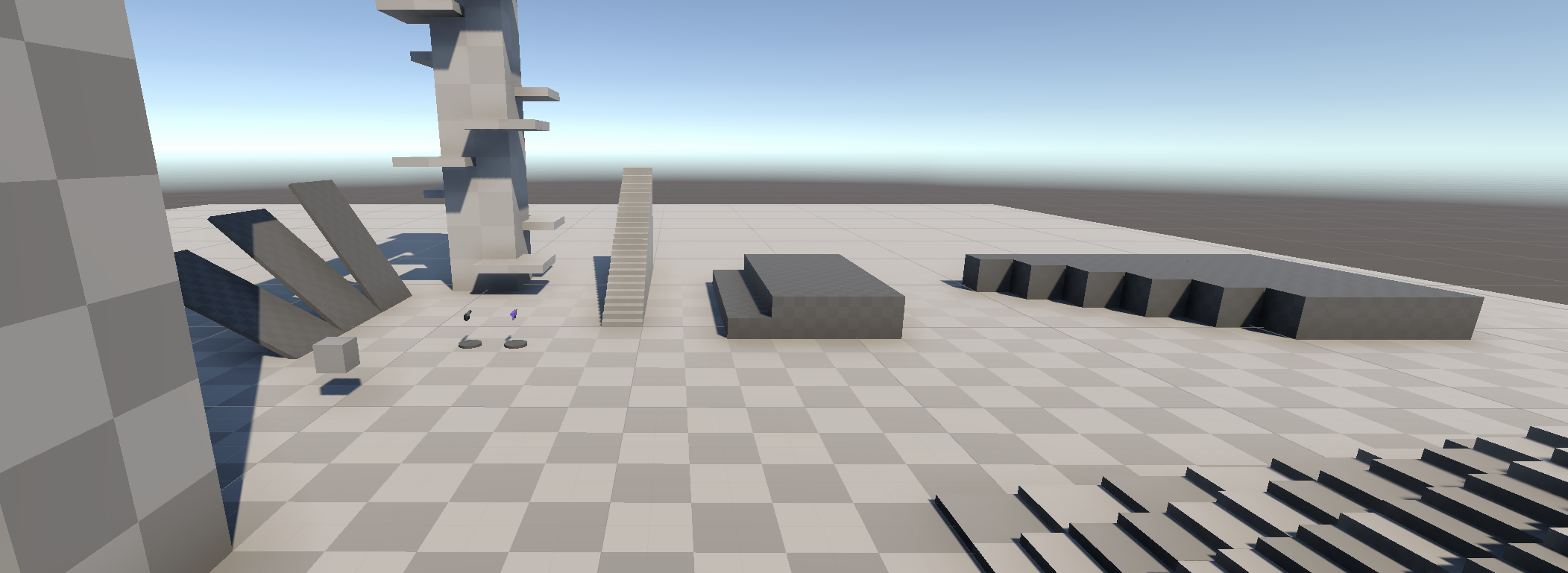
Something we use almost always when starting a new project is whitemesh. We build blocks out of nothing and the very first thing is to get rid of the flat color, and add some kind of sense of scale by applying an uniform pattern on our environment.
Whitemesh block-outs in production often use this kind of shader as a placeholder, in order to simulate the response of a later material, and also keep track of the scale of the world.
In game engines, there are often a default checkerboard texture available, for example the Default-Checker-Gray that is part of Unity’s default resources. Using it can be extremely useful ; however, when blockin out we often scale our objects using non-uniform scaling, thus stretching the checker texture and losing all sense of scale.
There are many methods to avoid that issue with textures, the most common being triplanar mapping, a quite expensive method that uses 3d world positions of pixels instead of UV Texture Coordinates.
If you are in need of an expensive solution early on your project (for instance if you want to increase the price of one pixel, which can be a good idea if you plan on getting expensive on your project), you could go the triplanar way.
However, there are other solutions that can help you come up with something really fast, without any textures. This article presents one of the use cases, in unity, for URP, but it also works for other render pipelines, and even for Unreal Engine, or any other engine ! As long as you can get pixel positions in world-space, and normal vector in world space as well.
Note : for the purpose of this tutorial, I used a quite simple tool to make SVG figures : Boxy SVG, it is available as a web app / plugin for chrome and opera. And a desktop app on mac and linux. (Don´t know why, firefox and windows are let down)
Principles of the shader
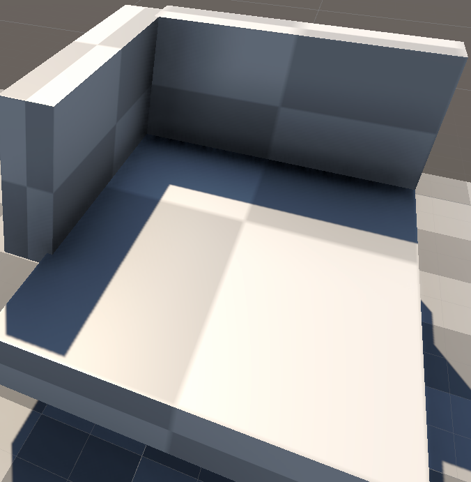
The shader that we are about to make is basically a Procedural 3D Checkerboard that will act as a black and white mask. This mask can be used for instance for material properties blending: One material for the Odd cells (dark), and one for the Even cells (bright).
Our pattern will be revealed on the mesh surface based on a 3D world of voxels of odd, or even material. And it will be revealed as the intersection of it with the Mesh surface.
In layman’s terms, if a given pixel of a mesh is inside a white cell, we display it using the white material properties, otherwise the other.
In 2D that would look like this, the mesh (bright) reveals the invisible, infinite checkerboard grid.
What’s interesting with this conecept is that mesh is independent from the grid. So the checkerboard is always correct in the world, no matter the rotation or scale of your object.
First proof of concept : 1D, then 2D
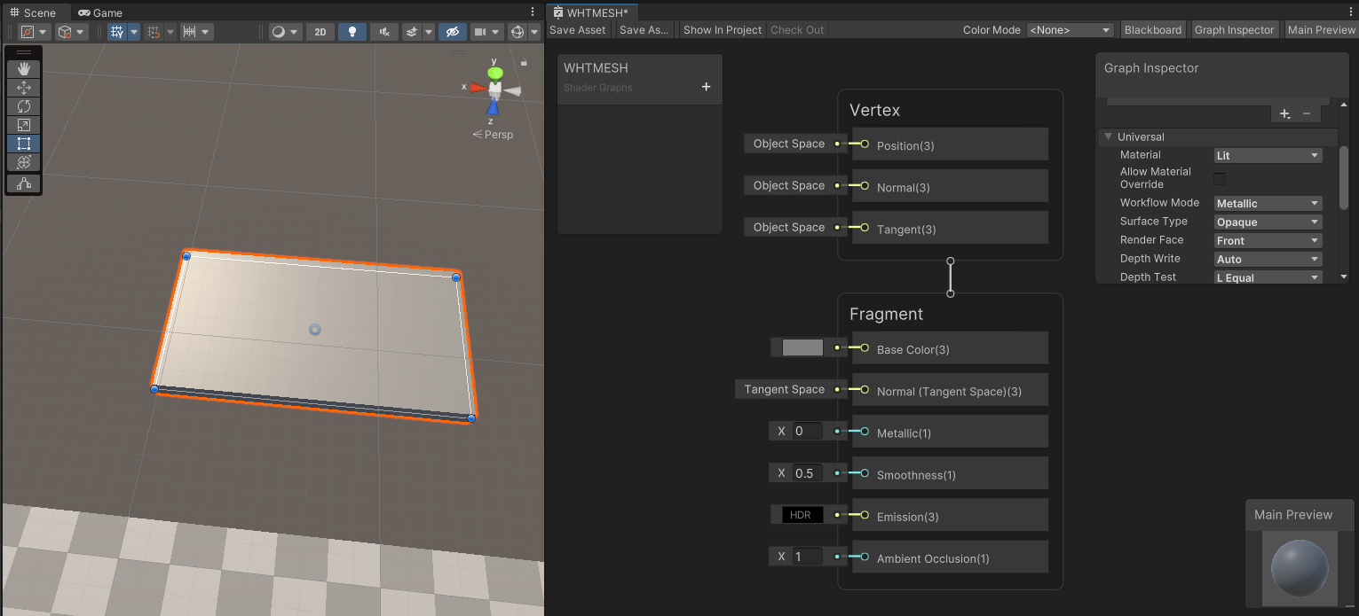
For starters, we are going to create a blank lit shadergraph, make a material out of it, and apply it to a stretched cube in a scene.
The first thing we are going to do is to reveal the World Positions as UV Color for our mesh. To do so, we are going to use the Position (World) node, and Fraction.
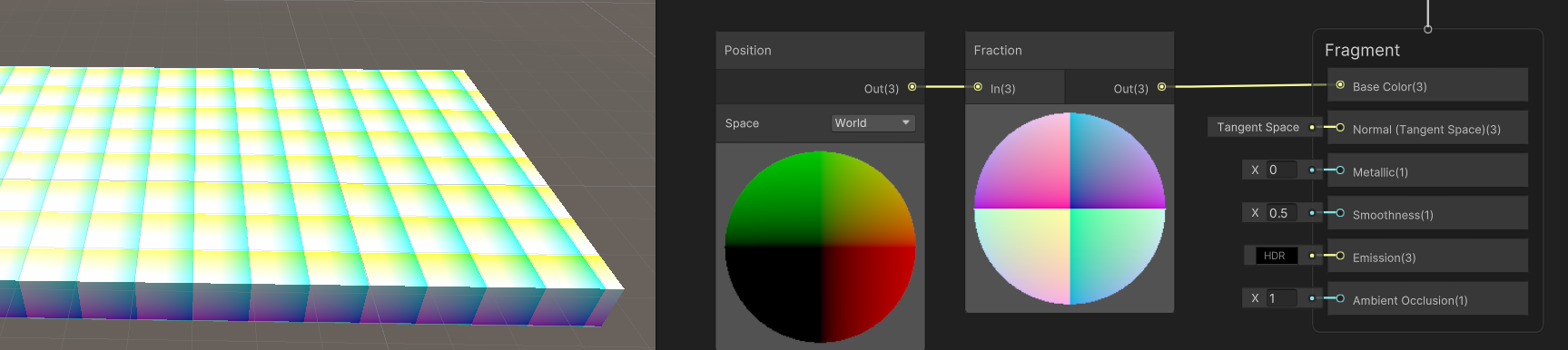
When used in base color, these fucntion will output the positions of the pixels in world space, and the fraction node will only keep the fraction value between 0.0 and 1.0, so you will see a gradient of R, G, and B repeating every 1 unit.
This is great, but now how do we make a checkerboard out of this?
In order to create the checkerboard, we are going to find the math function that alternates odd and even cells, infinitely. This function acts like this:
-
If I am between 0 and 1, I am black
-
If I am between 1 and 2, I am white
-
If I am between 2 and 3, I am black anew
-
…. wait, stop this repeats infinitely, i won´t do that all night.
So if we were to make this infinite function we would say that:
-
If my integer part of my coordinate is even (0 to 0.99999) : BLACK
-
If my integer part of my coordinate is odd (1 to 1.999999) : WHITE
-
Rinse and repeat every 2 units.
Something that is interesting is that we have all that we need already in shaders:
-
Check the integer part can be made using floor or ceil. Floor returns the lower integer (for instance 1 for 1.5), while ceil will return the upper integer (for instance 2 for 1.5). In our case, we will use floor
-
If we were to repeat every two units, we have the modulo operation. This makes the value repeat every N. A modulo of 1 is called fractional part, so it repeats between 0 and 0.999999….. A modulo of two will repeat the range between 0 and 1.9999999.
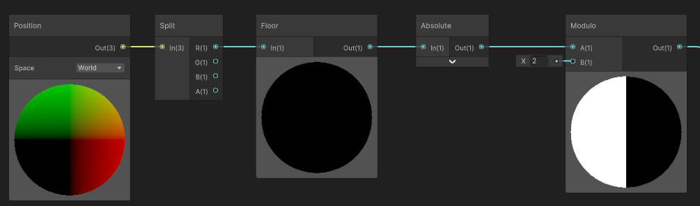
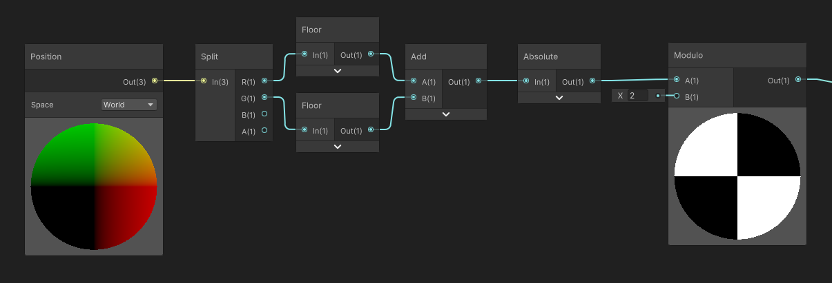
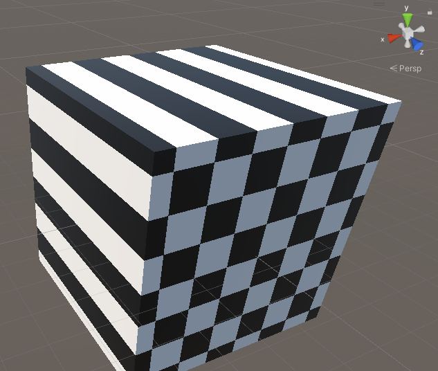
Knowing that, let’s try this on the X axis of the world position:
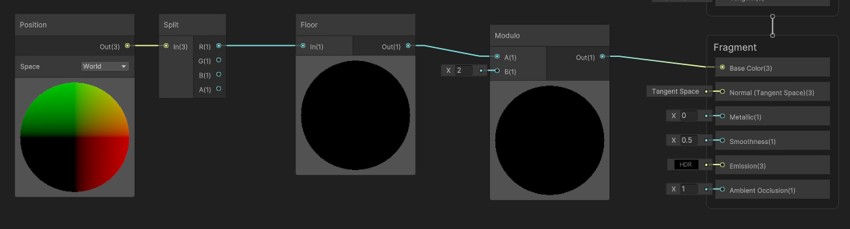
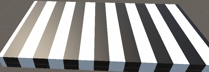
And see the results in the world:
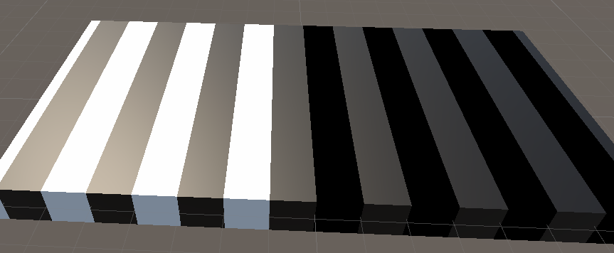
Ok, we have a slight problem here: the right part of the mesh is pitch black. Which reminds me of something : This part is in the negative X coordinate of the world. So if we were to find the lower integer, for example for -0.5, it would be -1, and for -1.5, it would be -2 !
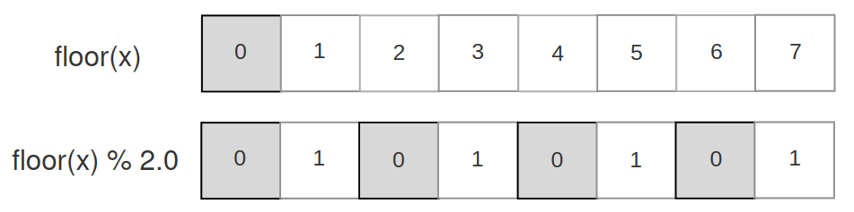
The floor problem, summarized
When we work only with positive values, the floor of x, modulo by 2 works as expected.
However, when dealing with negative values, we get some kind of inversion, which seems quite natural, as the floor will return the lower integer : -1 for the range [-1…-0.0001], -2 for the range [-2 …. -1.00001], etc.
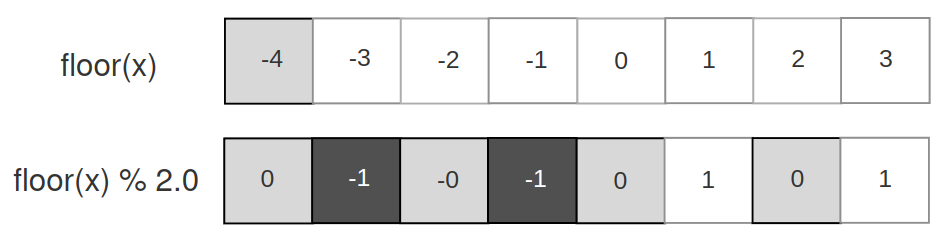
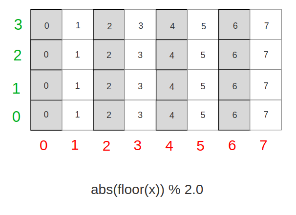
if we take a look at how positive values behave, we get something of interest : even values get black, odd values get white. But it is inverted when negative. Why don´t we remove the sign ?
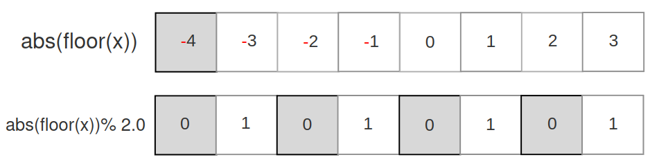
In that case, we get what we expect : inversions. So let’s apply this math back to the shadergraph :
And here we are! Correct inversions for the positive sign.
Extrapolating in 2D, then 3D
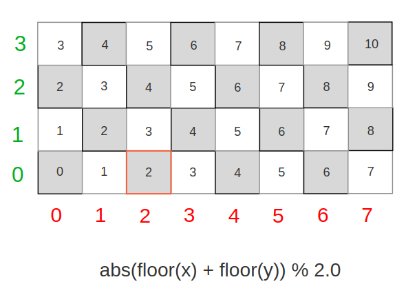
So here we are. We get our checkerboard in 1D, now, it is time to make it work on any axis. If we draw again our chekerboard, now in 2D, only with our function based on X coordinates we get this :
Now, what do we need to alternate values every Y line ? Judging by our parttern, we would probably need to offset every line by 1, meaning every line is offset by the integer part of its coordinate : floor(y)
Let’s apply this coordinate change in our shadergraph:
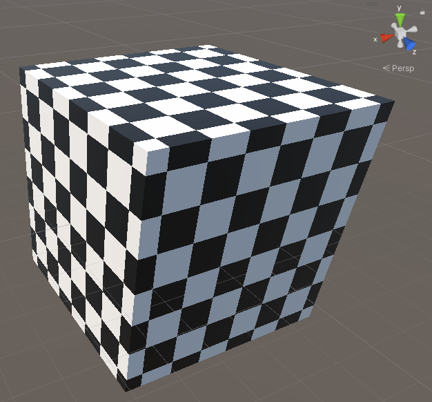
Now it works on both X and Y axes.
Finally, let’s extrapolate again, and add the offset for the Z coordinate.
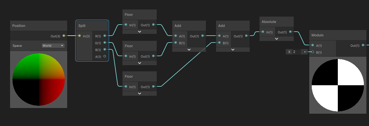
Was not the hardest part, it just works.
Going Further
Now, we get our 3D Pattern as a function, first, we can simplify the graph to this. Instead of using 3 floor, we can use a floor of the Vector3 position, then add every component. It is absolutely identical.
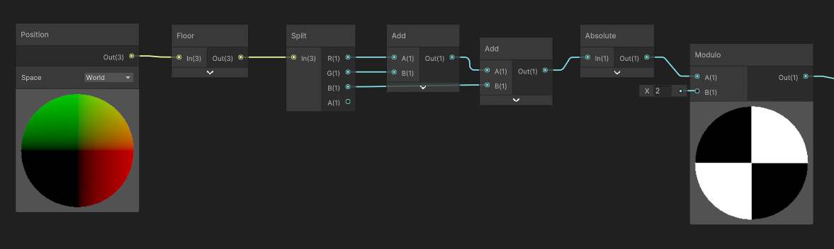
Floor / Modulo and Interpolation Precision
Now, let’s take a look at our cube, when we put a size of 2 : we get a ton of garbage, and noise, just like Z-fighting. But in our case this is not Z-fighting.
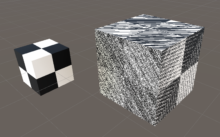
The artifact we see here is due to interpolation of vertex values of the world position. In shadergraph, the generated position is computed in the vertex shader, then interpolated when drawing the triangles. However we´d expect that all the values to be the same right? In our case, the extent of the cube in each axis is from -1 to 1. We are at the exact coordinate where the modulo and/or the floor will change the value.
The reason behind that is some kind of imprecision in GPU rasterizer (the part of GPU that determines, then draws the triangle’s pixels) when interpolating the values between the vertices of a triangle.
While in most cases this issue is not noticeable, here we can observe the imprecision : we are supposed to go from -1 to -1, so we’d expect the value to be exactly the same on all pixels : in practice, all the intermediate pixels values can shift a little, -1.00001 to -0.99999 for example, and that’s just enough to trigger the problem.
So, how do we fix the problem?
Short answer, we can´t. However, we can try to reduce the problem in common cases. The problem did happen when we were using integer values as scale, and/or positions. That is a common case while blocking out levels, and even meshes we author follow very often integer coordinates.
Also, if the problem did happen at any arbitrary other value threshold, it would be really diffucult for a user to manually place/scale the object so the problem appear intentionally.
A solution I found in order to fix the issue is to apply a slight offset to the world position we read, so it doesn´t overlap the integer anymore. We don´t change the geometry, only the values we read for the world position in our checkerboard function.
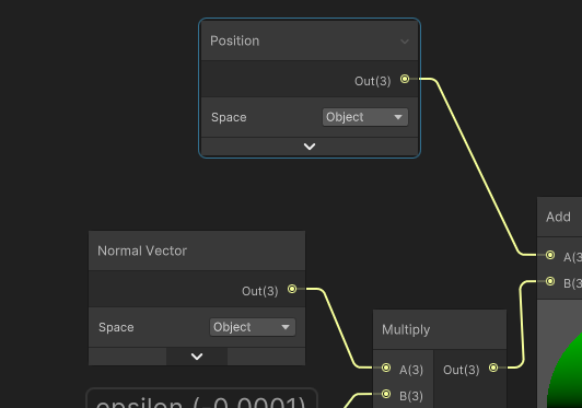
In order to do that, we can assume that the mesh is slightly smaller than it actually is. And to compute the shrunk-down position, we will apply an offset based on the normal of the mesh.
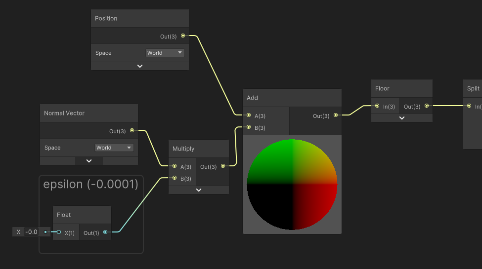
In the shadergraph, I multiplied the Normal vector by an arbitrary epsilon value that needs to be small , but big enough to alter the problem.
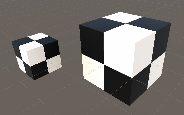
So, here we would have the interpolation error slightly offset : now the error happens between -0.99985 and -0.99995, we do not cross the integer value anymore, so the problem is solved for our case.
Local Space Checkerboard
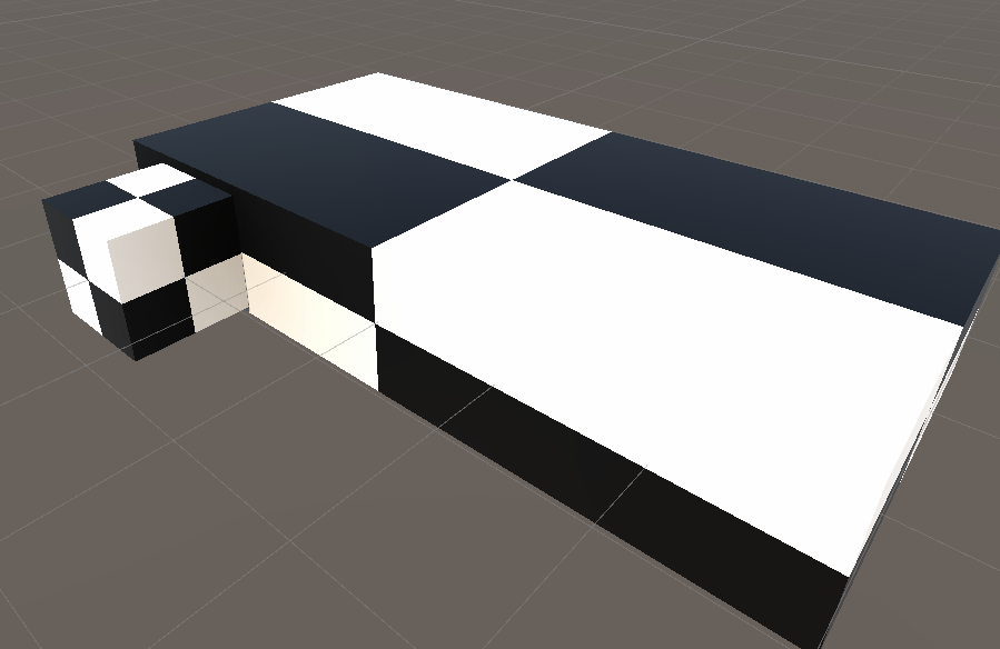
Sometimes, we also want moving objects keep their checkerboard while moving around. However in our case, we used world position/normals to compute the mask.
If we change the coordinates to object space, it seems to work at first sight,
However when we scale our object, the checkerboard doesn´t follow the scale anymore.
The problem here is that we read the values of the object before it is being scaled by the transform matrix. While it can be intended, it is not really interesting to read the metrics.
The solution is to apply the object scale to the object position coordinates.
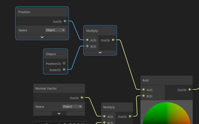
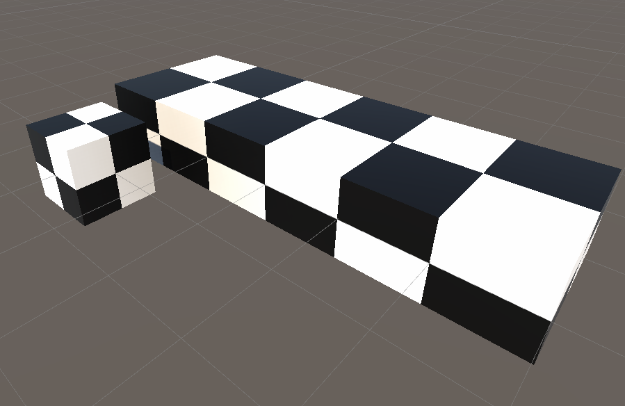
Now it behaves correctly
Wrapping up
We can see in this example a quite simple function that you can use for your materials, that doesn´t require any textures and that you can extend to your liking. Of course, you can also use a scale to the input position to control the tiling of the checkerboard.
Something I also used in my shader is to fade out the checkerboard pattern in distance to avoid too much aliasing. It can be read from the Screen position (Raw) node, in the alpha channel.